

CD Storage Container Analysis Part 1: Base

This is part 1 of a three-part part analysis blog. Over the three parts of this blog we will be analyzing the three pieces of a CD storage container assembly. While not many of us are still using CD’s, most of us remember a time when the entire world was. This case originally held multiple blank CD’s which could be used for data storage, or adding music/ videos to. Now that we are familiar with how this case was used, let’s dive in and find out how it was made

This blog will focus on the manufacturing analysis of the CD storage container base. The base assembly consists of two parts - the “base” and the “post”. This blog will cover only the design aspects of the base.
Base General Design Elements
The base contains a few notable design elements. As pictured above, we can see the base is given a series of ribs to aid in the structural rigidity of the part. Ribs help to aid the stiffness of the part, without increasing the average (nominal) wall thickness of the part. This helps keep cycle times fast, and material usage low. This part also features a snap feature that mates with the cover of the assembly. The snap feature will be outlined in the ejection section of this blog.
Ideally, this part would be combined with the post to eliminate post processing assembly operations. One of the main benefits of the injection molding process is the ability to combine parts such as these to make one large complex part.
Base Manufacturing Method
This part is injection molded; Rightfully so as it features ribs, and other difficult to form geometry.
Base Parting Line Location
In order to utilize the injection molding machines clamp tonnage and platen area most effectively, the parting line runs along the surface of the bottom of the base. It should be noted that the parting line does not run along the ribs, but rather along the large flat surface of the base where the gate vestiges lie.

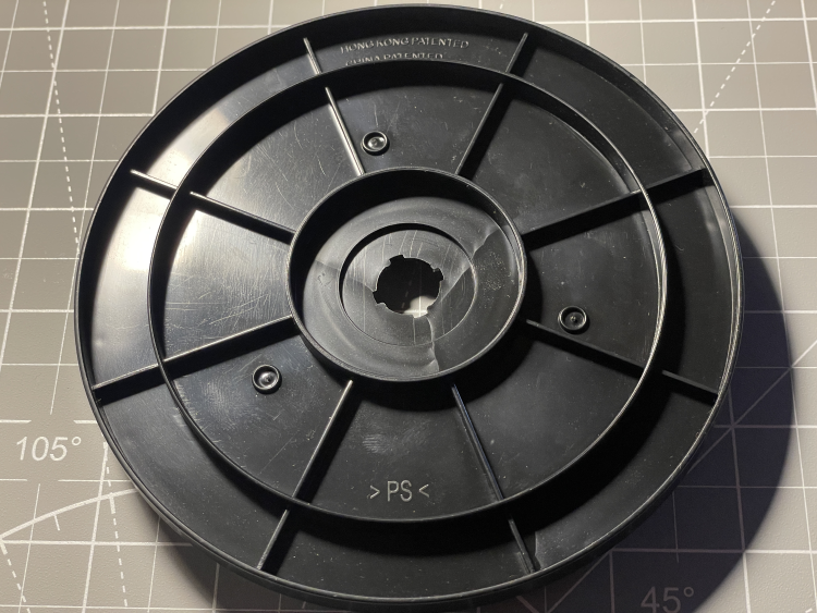
Base Gate Location
The base appears to be gated at three locations (see annotated picture above; gates in orange). Given the “small” size of this part (diameter = ~5.5”), it seems unnecessary to utilize three gates in this situation. Along with increased mold complexity, using three separate gates (annotated in blue below) creates three weld lines that would not be present otherwise.
Having this many weld lines creates multiple areas on this part could that fail prematurely. It is worth nothing that this part does not have any real structural or mechanical requirements, but it is still typically poor practice to gate with this many weld lines unnecessarily.
Due to the pinpoint gates not being located on the parting line, and the lack of witness lines indicating a hot runner drop/ nozzle, we can deduce this was most likely the product of a three-plate cold runner mold. The main advantage of this mold type is automatic degating, and gate location flexibility.


Base Ejection
The base is ejected using 8 ejector pins (pictured above, left) on the side of the base opposite the gates and a combination of lifters/ slides to release the undercut formed to interlock the base with the lid (pictured above, right). The manufacturer likely used so many ejector pins to distribute the ejection force evenly across the part.
Material Selection
On the bottom of the part, there is a molded in material indicator “>PS<” for polystyrene. PS is the right choice for this part, as it is rigid and low cost. It is likely a low cost carbon black concentrate/ masterbatch was used at a low percentage with a virgin PS resin to give this product its color.
This concludes the CD storage container “base” part analysis blog. The next part analysis blog will cover the second part of the CD storage container assembly which mates to the base, the “post”!